|
|||||||
| Members' SSPs A place to post up pics of your SSP, whether restored, in-progress, or somewhere in-between. |
 |
|
|
Thread Tools | Display Modes |
|
#101
 04-15-2017, 09:33 PM
|
||||
|
||||
|
Its been raining and storming here for the last week, and I had some extra time, so it seemed like a good time to build the fuse block for 0327. I didnt have much to go on in trying to figure out how CHP built their custom fuse block for the 1982 Mustang, so I looked at what others have done for various years, the 1984 wiring diagram I posted earlier in this thread, and started a design.
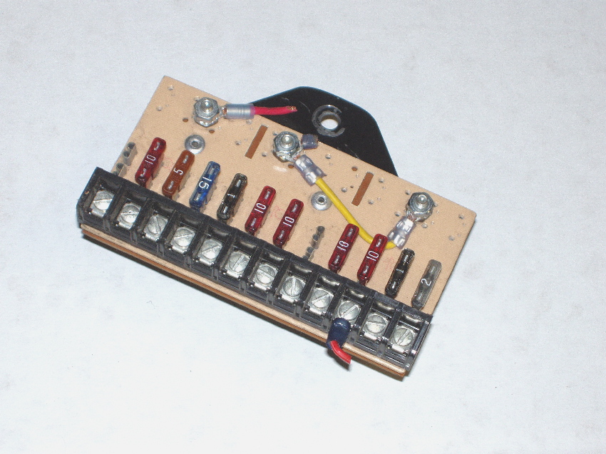
The first thing I looked at was where I might put it. Under the dash, drivers side, above the clutch pedal, there is a lot of room. Then, what materials were available. Any number of fuse blocks are available online, from 4 circuits to 12 or more, some very simple, others more complicated and expensive. The main problem is that, as shown in the 1984 wiring diagram, there are 10 circuits, fed by 3 sources. All of the fuse blocks I could find had provision for only one input connection. So I settled on the 4-circuit block shown in the first photo, Fuse Block Purchased, below. You can get them online from Amazon or eBay, or elsewhere. They are very inexpensive. I ordered 3; that would enable each one to be powered from the 3 sources (Mustang stock fuse block, CC1 B+, and CC1 RC) independently. I needed 10 fuses; this combination gives 12 but on two of the blocks I could just leave one circuit unused. I had a piece of insulating board material in my electronics parts bin; it is about ¼ thick, rigid, and is ideal for mounting the fuse blocks. I laid them as shown out in the next photo, Fuse Blocks Mounted, leaving sufficient space in between to be able to run connecting wires in with spade lugs without bending the wires too close to the lugs and putting stress on the connections. I like ring and spade lugs but you have to be careful; even with the right-sized lugs, crimped with the right tool, the wire can pull out or loosen if strained. After mounting the fuse blocks, the next step was to locate where the input power leads would come in and attach. I used a piece of solid bare #14 wire (from household Romex type cable to connect all the terminals on one side of each fuse block, creating a bus. The next photo, Input Wire In Place, shows all 3 with the solid wire soldered to each fuse block terminal. You have to be careful when soldering to the fuse block terminals; they were intended for spade lugs and if you overheat those terminals it can melt the plastic block. The free end of each copper wire goes to a ring connector screwed down to the board. When connected in the system the incoming power line ring connectors will go to those terminals. The other side of the fuses are where the powered devices will connect, using spade lugs. In order to protect all the wiring from possible contact, to give a finished appearance, and enable a means to label the fuses, I needed a second board to go on top. I took a piece of prototyping board, available at any electronics supply house, and carefully marked then cutout sections using a Dremel tool so it would fit over the 3 fuse blocks. This board type is very convenient because the pattern of the pre-drilled holes makes it easy to mark and cut and line things up. It is also very easy to cut with the Dremel. The next photo, Top Cover, shows this board in place. The following photo, Side View With Both Boards, shows it in place with standoff hardware mounted in between so the top board can be fastened down. With the basic assembly done, the next step was to figure out how to mount this assembly. Many measure, fit, mark, trim, etc. trips under 0327s dash later, I had it figured out. By the way, I did what my mechanic friend advised if doing a lot of work under the dash: I took the drivers seat out. This allows you to lay on your back and work much more comfortably. I even folded up a large beach towel as a pad to lay on, and it worked well. I also fabricated an aluminum mounting bracket that picks up a hole in an existing Mustang bracket used to mount a relay or a flasher, then did final trimming and fitting. Fabricating the bracket enabled a really secure mounting that gets this fuse block well up under the dash, out of view but easily accessible, while not interfering with clutch operation. The last photo, Finished, shows the completed assembly, with mounting bracket installed. Input sources and powered circuits are labeled. I printed the labels on paper, cut them out, and glued them. I need to pick up some 2A fuses to complete populating the fuses. The unused (unlabeled) fuse positions are handy for holding spares. Final size for the assembly is 10 ¼ long, 3 ½ wide, and 1 5/8 thick. Since I had most of the materials in my shop already total cost was less than $20. When I finish the wiring harnesses, and connect the fuse block, I will post some pics of it installed and wired.
__________________
******************************************* 1982 CHP 0327 
|
|
#102
04-16-2017, 01:44 AM
|
||||
|
||||
|
Amazing work, Steve! Do you double as an electrical engineer in your second life after the CHP? 👍🏻
__________________
1982 CHP Mustang Coupe, Unit # E870567 **SOLD to chp1982** 1988 Mustang 5.0 LX, Unit # HP 43 (Wyoming Highway Patrol) 1991 Ford Crown Victoria S (Brentwood, CA Police Dept/Cinema Vehicle Svcs) 1992 Chevrolet Camaro RS B4C, Unit # 360 (Colorado State Patrol) **SOLD BACK TO CSP** 1996 Bronco XL 5.8L (California Highway Patrol)
|
|
#103
04-16-2017, 08:41 AM
|
||||
|
||||
|
Great job and excellent write-up. Thanks for sharing.

__________________
Bill Jr. To everyone out there, wherever you are. Remember, the light at the end of the tunnel may be the police chasing you down in their own Mustang!
|
|
#104
04-16-2017, 12:13 PM
|
||||
|
||||
|
Quote:
It's supposed to be rainy again the next few days, which means inside work. Next up will be completing the wiring harnesses and installing the Federal TS100 outside speaker.
__________________
******************************************* 1982 CHP 0327
|
|
#105
04-16-2017, 01:41 PM
|
||||
|
||||
|
Very nice work. Here is a shot of a CHP fuse block I owned at one time. John S. (John10608) has it now.
|
|
#108
04-18-2017, 06:27 PM
|
||||
|
||||
|
It was cloudy and cold again today, a perfect day for inside work. I had recently received the 100W outside speaker purchased on eBay, so I thought this would be a good day to install it.
The TS100 is a little larger than I expected, and is heavy, no doubt due to having a large permanent magnet in the coil area. The first thing to do was look at 0327 to see where it would go and what I could take advantage of from the past. On 0327, the original had been installed on the drivers side. That was obvious because there was a rectangular cutout in the lower bumper near the LF corner, and I could see where CHP had cut part of the plastic splash protection out on the inside of the LF fender to enable access to the area inside. I took the speaker assembly and tried fitting it into that area. I was hoping to see an indicator of what type of mounting bracket CHP had used and where it was, but there was only one obvious hole drilled in the underside of the frame that might have been used. It was inconclusive. So I knew I would have to fabricate something. The speaker came with a mounting bracket that I couldnt use as is, but it did pick up two of the mounting holes of the coil housing. So I modified the bracket, then fabricated an L bracket that would mount to the underside of the frame and attach to the modified speaker bracket. I used 1/8 stainless steel sheet to make the L bracket; it had to be strong and SS would prevent rust. It was some work and there were several hours of trial fit, marking, and modifying to get it right. I wanted it securely mounted, tucked in as much as possible, but not touching or too close to the radiator or anything that could damage it from contact and vibration. The most difficult part was the plastic air intake snorkel tube the Mustang uses (on each side). It takes up a lot of room in there and one edge of it pressed against the speaker horn and prevented it from going far enough into the well to enable square and a well-located mounting for the assembly. I dont know what CHP did; I wonder if they had a TS100 with a slightly smaller horn? I cut three slits in the open part of the snorkel tube to enable it to flex where the horn pushed against it to relieve the stress. Then I drilled three pilot holes in the underside of the frame, and mounted the L bracket with heavy-duty self-drilling screws. I had already run the wires into the area, and I wanted to keep the connectors the speaker came with, so I spliced the wiring by soldering them then using shrink tubing to protect the splices. I also used plastic flex tubing to protect the wires all the way from where they came through the firewall; I really like the look of that tubing. You can use regular speaker wire for this, 16 or 18 gauge is fine. There was no way I could see to mount the unit so the speaker horn is oriented the same way as the cutout in the front bumper, or get any closer to it without cutting out a large piece of the air intake snorkel. So the speaker horn is oriented 90 degrees different than the cutout, but everything is lined up, brackets are straight, so Im good with it. As soon as I get the CC1 and MPA2 installed I will be able to test.
__________________
******************************************* 1982 CHP 0327
|
|
#109
04-18-2017, 11:32 PM
|
||||
|
||||
|
Great write-ups, Steve.
Here is a picture of the mounts that CHP fabbed up for the siren speaker. It's in the CHP resto doc also. I know it's a newer car than yours, but I'm pretty sure my '82 still had it there also. http://www.specialservicemustang.net...CHPspeaker.jpg
__________________
Mike '82 SSP (Marketing Order) '83 Colorado State Patrol #202 '83 Texas DPS '85 Florida Highway Patrol #1422 '93 Florida Highway Patrol #1187 '93 Florida Highway Patrol #1363
|
|
#110
04-19-2017, 12:27 AM
|
||||
|
||||
|
I looked at that photo carefully before starting this and the '82 seems somewhat different in that area. A bracket going between the frame and the lower edge of the fender would have dropped the speaker down substantially lower than the underside of the body parts, and I didn't want to do that. The speaker in the photo looks, scale-wise, smaller than the one I have, and would also have had to be substantially smaller to look anything like the mounting in that photo.
As soon as I get the MPA2 cable done, I can wire everything up and test it.
__________________
******************************************* 1982 CHP 0327
|
|
|
|


 Linear Mode

