
|
|
|||||||
| Members' SSPs A place to post up pics of your SSP, whether restored, in-progress, or somewhere in-between. |
 |
|
|
Thread Tools | Display Modes |
|
#82
 03-24-2017, 08:02 PM
|
||||
|
||||

Thanks for that write up and information Steve. There's more and more of these cars turning up and the owners can use it. 👍🏻
__________________
1982 CHP Mustang Coupe, Unit # E870567 **SOLD to chp1982** 1988 Mustang 5.0 LX, Unit # HP 43 (Wyoming Highway Patrol) 1991 Ford Crown Victoria S (Brentwood, CA Police Dept/Cinema Vehicle Svcs) 1992 Chevrolet Camaro RS B4C, Unit # 360 (Colorado State Patrol) **SOLD BACK TO CSP** 1996 Bronco XL 5.8L (California Highway Patrol) 
|
|
#83
03-25-2017, 12:13 PM
|
||||
|
||||
|
Wiring Harnesses
Eric, previous owner of 0204, was kind enough to email a scan of a vintage wiring diagram from 1984. Using it as a guide not only for connections but also wire colors and sizes, I am putting together a set of harnesses. It doesn't seem difficult; but there are a couple of things on the drawing (attached below) that I don't know what to do with:
1. A Red wire going from the 1.5A fuse of the RC fuses to something labeled "M. Box". I haven't figured out what the M. Box is. "RC" probably means Radio Console or similar, because other fuses from that block supply power to the scanner and the Micor. 2. A yellow wire going from the 10A fuse on the B+ fuse block to the "Repeater". I think this would run all the way to the trunk to power a unit located in the trunk. I think that is the same repeater that is also connected to the small whip antenna mounted on the center rear portion of the roof. Back in the day I always thought that small antenna on the roof was for the Regency scanner. I wish I had paid more attention to details then, took photos, etc.
__________________
******************************************* 1982 CHP 0327
|
|
#84
03-25-2017, 12:21 PM
|
||||
|
||||
|
One More Thing...
Shotgun Release Switches
The shotgun lock release switches. The diagram shows 3 methods of activating the shotgun rack release. My memory of this is cloudy because of all the many other patrol cars I have driven over the years but I think I remember two switches and a key. The switches were one under the dash (pushbutton) and possibly one on the CC1. Both active only when the ignition key is on. Then a small key on the ignition key ring that would open the shotgun lock. Wish I remembered better.
__________________
******************************************* 1982 CHP 0327
|
|
#85
03-25-2017, 06:49 PM
|
||||
|
||||
|
Quote:
__________________
******************************************* 1982 CHP 0327
|
|
#86
03-25-2017, 09:28 PM
|
|||
|
|||
|
Thanks, Steve! The fleet is looking great. Regarding rodents, I bought the following and have been very pleased.
https://www.amazon.com/gp/aw/d/B00J1...s=rat+repeller
|
|
#87
03-26-2017, 05:47 PM
|
||||
|
||||
|
Quote:
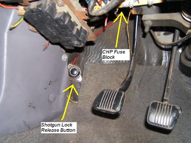 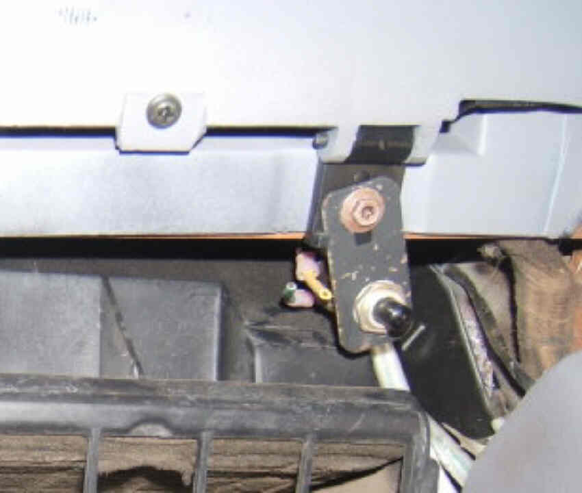 Here's a shot of the underdash switch in my car. I made up a reproduction bracket and used as close as i could come to the original style switch. 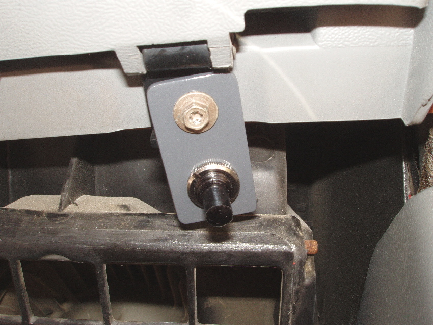
|
|
#88
03-26-2017, 06:40 PM
|
||||
|
||||
|
Thanks, Michael, that's very helpful. I think I was confusing the shotgun release buttons and the key with later Crown Vics I've driven that had a momentary rocker switch on the lights control boxes to release the shotgun. They also had a key to unlock it.
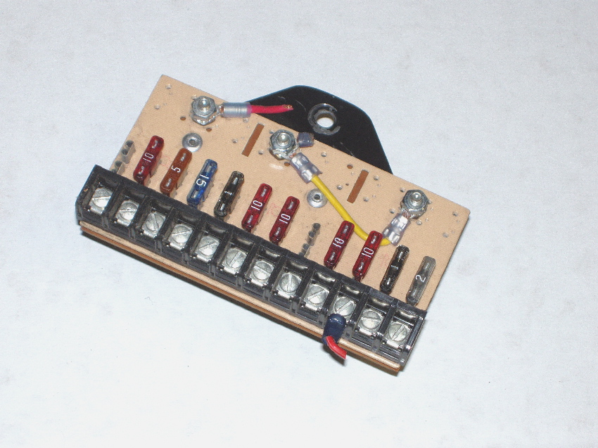
I'm going to check 0327 to see if anything is still left. But with your info, it shouldn't be too difficult to recreate them. I see your CHP fuse block is shown. Is that the original location? I thought I saw something somewhere mentioning they were under the hood, but I don't see any good place to put them.
__________________
******************************************* 1982 CHP 0327
|
|
#89
03-26-2017, 08:22 PM
|
||||
|
||||
|
Quote:
|
|
#90
03-27-2017, 05:08 PM
|
||||
|
||||
|
Today I spent a few hours revealing 0327's spotlight and antenna ball mounting holes. For the spotlights I used a cylindrical sanding tool with a Dremel and sanded the paint away carefully to show the Bondo spots. Once they were visible I used an Xacto knife to carve away the bondo (first photo). I wanted to be very careful not to enlarge the mounting screw holes.
Removing about a quarter inch of Bondo inside the trunk where the antenna mount is was much more work. I had to be careful because there was Bondo on both sides of the metal. I didn't want to knock any of the outside Bondo off or damage the metal shape and create more body work. Carefully chipping away as much Bondo on the inside as I could with a putty knife then grinding the rest away, I could see where the three bolt holes and the center hole were from the trunk side. I then drilled the bolt holes and the center hole, using the Dremel tool once again to remove the rest of the Bondo to the original-sized center hole. (second and third photos) The ball mount fits perfectly. It was a good day for 0327. A little at a time, just keep moving forward...
__________________
******************************************* 1982 CHP 0327
|
|
| Thread Tools | |
| Display Modes | |
|
|





 Linear Mode

